<?xml version="1.0" encoding="utf-8"?><feed xmlns="http://www.w3.org/2005/Atom" ><generator uri="https://jekyllrb.com/" version="3.10.0">Jekyll</generator><link href="https://normandunbar.github.io//feed.xml" rel="self" type="application/atom+xml" /><link href="https://normandunbar.github.io//" rel="alternate" type="text/html" /><updated>2026-11-08T17:01:25+00:00</updated><id>https://normandunbar.github.io//feed.xml</id><title type="html">Rants and Raves</title><subtitle>My blog for anything I fancy discussing in the ranting and raving about stuff departments! It&apos;s been around since 2009, you&apos;ve just never found it before! ;o)</subtitle><entry><title type="html">Debouncing Arduino Switches Without any Additional Components</title><link href="https://normandunbar.github.io//2026/11/08/debouncing-arduino-switches.html" rel="alternate" type="text/html" title="Debouncing Arduino Switches Without any Additional Components" /><published>2026-11-08T00:00:00+00:00</published><updated>2026-11-08T00:00:00+00:00</updated><id>https://normandunbar.github.io//2026/11/08/debouncing-arduino-switches</id><content type="html" xml:base="https://normandunbar.github.io//2026/11/08/debouncing-arduino-switches.html"><![CDATA[<h2 id="introduction">Introduction</h2>

<p>Switches need debouncing, usually. This is especially true if you are using Arduino Interrupts as even at the Arduino’s paltry 16 MHz clock speed, it can react to an interrupt from a bouncing switch many, many times. This will, inevitably lead to your LEDs not working when the switch is pressed, or flickering at all the wrong times.</p>

<p>Basically, if you are reading the switch to toggle an LED on each press, then if there are an even number of bounces, the LED will appear not to change. If there is an odd number, then the LED will appear to work. The problem is, the number of bounces is not consistent, and the results can appear random.</p>

<p>You could write a software delay to react to the first press, then wait for the switch to stop bouncing, then read it again to get the “final” state of the switch. The problem with this method is that the delay is hard coded and might not work for every switch. To change the delay needs a recompile of the code. In addition, if the delay gets too long, the switch might appear to be unresponsive, so the user may “hammer” it multiple times just to get a result.</p>

<p>Another workaround is to use external components to debounce the switch. This could be as simple as a couple of resistors, a diode and a Schmidt trigger; or you could use a MC14490P Hex Contact Bounce Eliminator IC to debounce up to six separate switches.</p>

<p>There’s no need! You can debounce one or more switches without resorting to unreliable delays or costly external components. In addition, the switch will respond correctly, no matter how often the user hammers it!</p>

<h2 id="caveats">Caveats</h2>

<p>This method works for up to two switches attached to <code class="language-plaintext highlighter-rouge">D2</code> or <code class="language-plaintext highlighter-rouge">D3</code> <em>only</em>. If you need more switches, you will need to consider configuring Pin Change Interrupts instead of the <code class="language-plaintext highlighter-rouge">INT0</code>/<code class="language-plaintext highlighter-rouge">INT1</code> interrupts used here.</p>

<p>The reaction to the button press will be delayed for as long as it takes the <code class="language-plaintext highlighter-rouge">loop()</code> to execute. If a single pass through <code class="language-plaintext highlighter-rouge">loop()</code> takes two seconds, then there will be a maximum of two seconds between the button press and the reaction to it. If the loop is short, then so will the delay between action and reaction.</p>

<p>This method is not suitable for use as an emergency stop button because of the delay mentioned. For that, you definitely need an interrupt and handler to ensure that the button press is acted upon <em>immediately</em>.</p>

<h2 id="how-it-works">How It Works</h2>

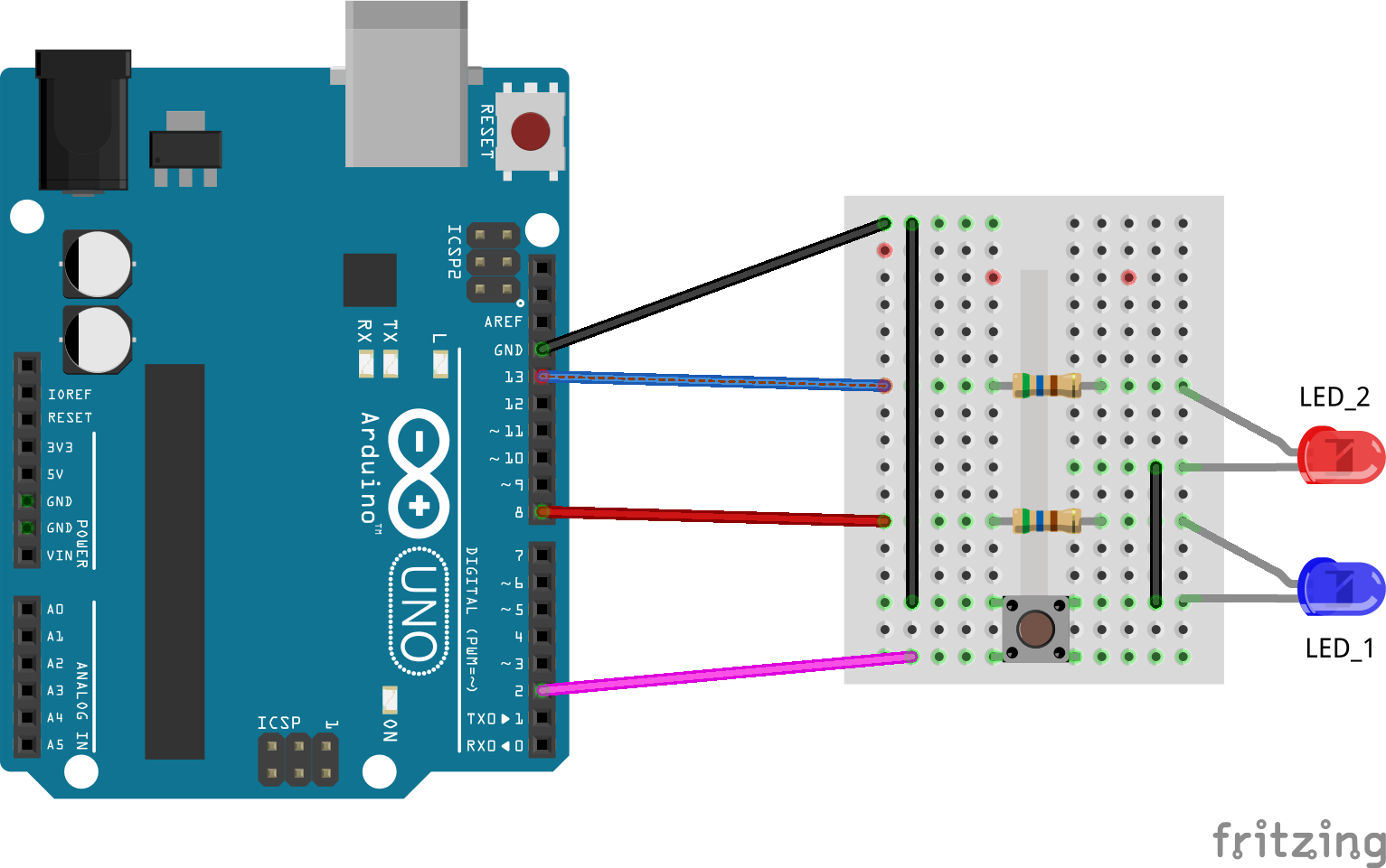
<p>In <a href="/downloads/Debounce_Events.zip">the demonstration sketch</a>, we will connect a single button switch to <code class="language-plaintext highlighter-rouge">D2</code> and configure it as <code class="language-plaintext highlighter-rouge">INPUT_PULLUP</code> to ensure it has a fixed “resting” state—never have input connections floating, it’s asking for trouble. An LED’s anode will be connected to <code class="language-plaintext highlighter-rouge">D8</code> via a 560R resistor, the cathode will connect to GND.</p>

<p><code class="language-plaintext highlighter-rouge">D13</code> has the usual built in, and tiny, LED on the Arduino board itself. You can, if you wish, connect an external LED to this pin. Use another 560R resistor to limit current.</p>

<p>The <code class="language-plaintext highlighter-rouge">setup()</code> function will configure the switch and the LED, and, will also configure the settings for an INT0 interrupt. The interrupt will be configured to trigger on <code class="language-plaintext highlighter-rouge">D2</code> going from <code class="language-plaintext highlighter-rouge">HIGH</code> to <code class="language-plaintext highlighter-rouge">LOW</code> <em>at any time, even in a <code class="language-plaintext highlighter-rouge">delay()</code> function call</em>. The INT0 interrupt, however, will not be enabled, only configured.</p>

<p>When the button is pressed, the ATmega328P notices, as if an interrupt had triggered, but only the interrupt flag is set. And this is where the debouncing happens. No matter how often the switch bounces, or the user hammers on it, the flag will (can!) only be set once.</p>

<p>The code in the <code class="language-plaintext highlighter-rouge">loop()</code> function might be in the middle of doing some useful work, or even, executing  the <code class="language-plaintext highlighter-rouge">delay()</code> function, it makes no difference. Once it gets around to checking the INT0 flag bit in the EIFR register, it will respond to the switch press, and toggle the LED.</p>

<p>Because we don’t have an interrupt handler configured, the flag bit remains set. Had there been a handler present, the bit would be cleared immediately, and would therefore be able to register another press (or bounce) and this is the cause of the code not working correctly.</p>

<h2 id="connections">Connections</h2>

<p>The wiring of the components is as follows:</p>

<p><strong>LED Connections</strong></p>

<p>D8 –&gt; 560R –&gt; LED_1+ 
LED_1- –&gt; GND</p>

<p><strong>Optional LED Connections</strong></p>

<p>D13 –&gt; 560R –&gt; LED_2+   (Optional)
LED_2- –&gt; GND            (optional)</p>

<p><strong>Switch Connections</strong></p>

<p>D2 –&gt; SW+ 
SW- –&gt; GND</p>

<p>See also the Fritzing generated breadboard diagram, <code class="language-plaintext highlighter-rouge">INT0_INT1_Debounce_Events.png</code>, elsewhere.</p>

<h2 id="arduino-code">Arduino Code</h2>

<p>At the global level, we have a few definitions for the button and the LEDs we use. Here we also define our interrupt flag bit in the <code class="language-plaintext highlighter-rouge">EIFR</code> register.</p>

<div class="language-plaintext highlighter-rouge"><div class="highlight"><pre class="highlight"><code>//--------------------------------------------------------
// The EIFR bit we care about, plus LEDs and switches.
//--------------------------------------------------------
const uint8_t INT_FLAG = (1 &lt;&lt; INT0);
const uint8_t LED_1 = 8;
const uint8_t LED_2 = LED_BUILTIN;
const uint8_t BUTTON = 2;
</code></pre></div></div>

<p>Next, in the <code class="language-plaintext highlighter-rouge">setup()</code> function, we need to configure our LED and Switch connections. As I mentioned, it’s not necessary to configure the switch as an input as we are “sort of” using interrupts, but it does make things better documented <em>and</em> we can configure the switch as <code class="language-plaintext highlighter-rouge">INPUT_PULLUP</code> to let us use a <code class="language-plaintext highlighter-rouge">FALLING</code> interrupt trigger.</p>

<div class="language-plaintext highlighter-rouge"><div class="highlight"><pre class="highlight"><code>    //--------------------------------------------------------
    // Configure the switch on D2 and LEDs. It's not strictly
    // necessary to configure the switch, but we need pullups
    // enabled. We could use external resistors, of course, to
    // pull the switch on D2 up or down.
    //--------------------------------------------------------
    pinMode(LED_1, OUTPUT);
    pinMode(LED_2, OUTPUT);
    pinMode(BUTTON, INPUT_PULLUP);

    //--------------------------------------------------------
    // Configure an INT0 interrupt on D2. We don't enable the
    // interrupt though as we will use a scan to check if the
    // switch on D2 was pressed "at some point". If so, we 
    // will toggle the LED on D8.
    // 
    // The EICRA.ISC01 and EICRA.ISC00 bit settings are:
    //
    // 00 = LOW (LEVEL, must be held low or nothing happens)
    // 01 = CHANGE
    // 10 = FALLING &lt;--- We are using this one.
    // 11 = RISING
    //
    // As the switch is pulled up, we look for a
    // FALLING change on it.
    //--------------------------------------------------------
    // We have to talk directly to the registers here as there
    // is nothing in the Arduino Language that will do this
    // for us without enabling the INT0 interrupt. We only
    // want to *configure* the interrupt, not *enable* it.
    //--------------------------------------------------------
    EICRA = (1 &lt;&lt; ISC01) | (0 &lt;&lt; ISC00);      /* INT0 */
}
</code></pre></div></div>

<p>The <code class="language-plaintext highlighter-rouge">loop()</code> function, in the sketch, simply checks to see if anyone, at any time, pressed the switch and if so, toggles the LED on <code class="language-plaintext highlighter-rouge">D8</code>. If this is detected, the flag bit for the INT0 interrupt <em>must</em> be cleared by writing a 1 to it. This is necessary because the sketch is not triggering an interrupt. If we didn’t clear it, it would constantly remain set so the LED would toggle each time through the <code class="language-plaintext highlighter-rouge">loop()</code>.</p>

<p>Regardless of whether or not the button was pressed, we toggle the built in LED on <code class="language-plaintext highlighter-rouge">D13</code>, and call <code class="language-plaintext highlighter-rouge">delay()</code> with a one second timeout. Normally, we would not use <code class="language-plaintext highlighter-rouge">delay()</code> in this manner—even given all the “blinky” examples out there—as the board is tied up for the duration of the delay call. We would use <code class="language-plaintext highlighter-rouge">millis()</code> and check if the delay has passed yet, in an ideal world, but I wanted to demonstrate that it still works, even with a <code class="language-plaintext highlighter-rouge">delay()</code> call in the code.</p>

<div class="language-plaintext highlighter-rouge"><div class="highlight"><pre class="highlight"><code>void loop() {

    //--------------------------------------------------------
    // See if an "interrupt" occurred on D2 or D3. Pressing
    // the switch should change the EIFR.INT0 bit. The flag
    // bit will need to be manually cleared by the code as we
    // are not triggering the INT0 interrupt.
    //
    // Once again, we need to talk directly to the registers.
    //--------------------------------------------------------
    if (EIFR &amp; INT_FLAG) {
        // Clear the INT0 interrupt flag.
        EIFR |= INT_FLAG;

        // Toggle D8 when the button press is noticed.
        digitalWrite(LED_1, !digitalRead(LED_1));
    }

    //--------------------------------------------------------
    // At this point, the code should be off doing a bit of
    // useful work, only checking the switch every so often.
    // We could insert a delay here to simulate the work done,
    // I tested with delays from 10 up tp 5000 and it "just"
    // works. In actual fact, no delay is necessary, but if
    // you have one of a decent length, you will note that the
    // switch does respond correctly, even if a delay is
    // noticed.
    //--------------------------------------------------------
    // NOTE: The switch will respond with a press once and
    // once only no matter how often the user hammers it, or 
    // no matter how bouncy the switch is. As soon as it goes
    // low when pressed, the EIFR.INT0 bit is set to indicate
    // a press. This bit is what we look for instead of always
    // reading the switch when we want to know if it was 
    // pressed.
    //--------------------------------------------------------
    // To simulate "real" work, we toggle the built in LED
    // once every second, and yes, we are using a delay! In
    // normal circumstances, the user would have to press the 
    // button in the time between the final delay() ending and 
    // the next one beginning otherwise the press would be
    // missed. With this setup, the press doesn't go missing
    // and the D8 LED will toggle when the built in LED next
    // toggles, assuming the button has indeed been pressed.
    //--------------------------------------------------------
    digitalWrite(LED_2, !digitalRead(LED_2));


   //--------------------------------------------------------
   // This delay(), as well as determining when the built in
   // LED will toggle, also determines when the button press
   // will be acted upon.
   //
   // It should be noted that such a setup is NOT SUITABLE if
   // the code is monitoring a safety cutout switch, for that
   // you defintely need an interrupt and handler.
   //--------------------------------------------------------
    delay(1000);
}
</code></pre></div></div>

<h2 id="breadboard-layout">Breadboard Layout</h2>

<p>The breadboard layout used for this sketch is as follows:</p>

<p><img src="/images/Debounce_Events.png" alt="Breadboard layout showing two LEDs, one of D8 the other on D13 and a button swtch on D2." /></p>

<p>Have fun.</p>]]></content><author><name></name></author><summary type="html"><![CDATA[Introduction]]></summary></entry><entry><title type="html">I have a new blog!</title><link href="https://normandunbar.github.io//2026/10/21/i-have-a-new-blog.html" rel="alternate" type="text/html" title="I have a new blog!" /><published>2026-10-21T00:00:00+00:00</published><updated>2026-10-21T00:00:00+00:00</updated><id>https://normandunbar.github.io//2026/10/21/i-have-a-new-blog</id><content type="html" xml:base="https://normandunbar.github.io//2026/10/21/i-have-a-new-blog.html"><![CDATA[<p>Well, after a wee while away, a conversion from WordPress to Hugo, and then a conversion from Hugo to Jekyll, it seems that “Rants &amp; Raves—The Blog” is back!</p>

<p>I’m not sure how much that might cheer you up, but stay tuned for some more ranting and a bit of raving too.</p>

<p>One thing I noticed, while making a few corrections and updates, checking links etc, was how often my original WordPress blog had been edited (hacked!) by someone who was not me. The piles of spam I had to edit out was quite astounding.</p>

<p>Something else I noticed, in the early years, especially 2009, I obviously was a very ranty person indeed. Some of the rants back then are quite astonishing. I must have mellowed in old age and retirement.</p>

<p>Cheers,<br />
Norm.</p>]]></content><author><name></name></author><summary type="html"><![CDATA[Well, after a wee while away, a conversion from WordPress to Hugo, and then a conversion from Hugo to Jekyll, it seems that “Rants &amp; Raves—The Blog” is back!]]></summary></entry><entry><title type="html">New Book - Arduino Assembly Language</title><link href="https://normandunbar.github.io//2026/09/01/arduino-assembly-language.html" rel="alternate" type="text/html" title="New Book - Arduino Assembly Language" /><published>2026-09-01T00:00:00+00:00</published><updated>2026-09-01T00:00:00+00:00</updated><id>https://normandunbar.github.io//2026/09/01/arduino-assembly-language</id><content type="html" xml:base="https://normandunbar.github.io//2026/09/01/arduino-assembly-language.html"><![CDATA[<p>I have a new book out! <em>Arduino Assembly Language</em>.</p>

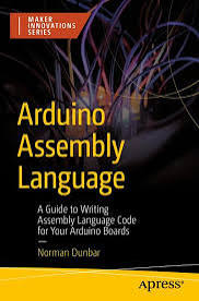
<p><img src="/images/ArduinoAssemblyLanguage.cover.jpg" alt="The cover of the Arduino Assembly Language book" /></p>

<ul>
  <li>
    <p>Get it from <a href="https://link.springer.com/book/10.1007/979-8-8688-2442-5">Apress</a>.</p>
  </li>
  <li>
    <p>Get it from <a href="https://www.amazon.co.uk/Arduino-Assembly-Language-Writing-Innovations/dp/B0G6JXT311">Amazon UK</a>.</p>
  </li>
</ul>

<p>The book will teach you everything you never knew you needed to know about Assembly Language on the Arduino Uno R3 and other boards with the ATmega328P.</p>

<h3 id="from-the-back-cover">From the Back Cover</h3>

<p>This book explores how to use Assembly Language within your Arduino sketches, directly from the Arduino IDE, without any external tools. By learning to write low-level code, you’ll gain the ability to reduce sketch size, increase execution speed, and achieve precise timing control, especially useful for tasks like bit-banging communication protocols.</p>

<p>It’s designed to be both educational and practical, helping developers and makers to reduce the size of their sketches, increase the speed of execution, and to get a much better understanding of how the Arduino hardware works. With a focus on clarity and hands-on examples, it’s ideal for developers and makers who want to push their Arduino projects further and gain deeper insight into microcontroller programming.</p>

<h3 id="example-sketch">Example Sketch</h3>

<p>The code below is created as a library, in the book, to allow easy access to the Watchdog Timer, and its ability to reset the board when it hangs up, as well as triggering an interrupt at regular intervals. For the sake of this example, just add the files to the skect and don’t worry about the original library.</p>

<h4 id="the-setup-function">The <code class="language-plaintext highlighter-rouge">setup()</code> Function</h4>

<pre><code class="language-C">#include "wdt_test.h"

void setup() {
    // The builtin LED is an OUTPUT.
    pinMode(13, OUTPUT);

    // Call the Assembly code to configure the WDT in interrupt
    // mode only (no resetting the board allowed) with an
    // interrupt generated every half-second.
    wdtEnable((wdtTO_500MS &lt;&lt; 8)|(wdtMode_Interrupt));
}
</code></pre>

<h4 id="the-loop-function">The <code class="language-plaintext highlighter-rouge">loop()</code> Function</h4>

<pre><code class="language-C">void loop() {
    // Nothing to do here. Ideally, the board
    // would be put to sleep.
}
</code></pre>

<h4 id="the-watchdog-timer-interrupt-handler">The Watchdog Timer Interrupt Handler</h4>

<pre><code class="language-C">// The WDT Interrupt Handler just toggles the built-in LED
// every time the Watchdog triggers an interrupt.
ISR(WDT_vect) {
    // Toggle D13/PB5.
    PINB |= (1 &lt;&lt; PINB5);
}
</code></pre>

<h4 id="the-header-file">The Header File</h4>

<p>In the Arduino IDE, click the button with three dots on it (…) and select “New Tab”. Give the tab the name <code class="language-plaintext highlighter-rouge">wdt_test.h</code> and paste the code below into that tab.</p>

<pre><code class="language-C">#ifndef WDT_H
#define WDT_H

#include &lt;avr/io.h&gt;

// We have to define our own constants to match the
// bit patterns for the various timeouts in the WDTCSR 
// register.

// Timeout macros.
#define wdtTO_16MS 0
#define wdtTO_32MS 1
#define wdtTO_64MS 2
#define wdtTO_125MS 3
#define wdtTO_250MS 4
#define wdtTO_500MS 5
#define wdtTO_1S 6
#define wdtTO_2S 7
#define wdtTO_4S 32
#define wdtTO_8S 33

// Watchdog modes.
#define wdtMode_Off (0 &lt;&lt; WDE)|(0 &lt;&lt; WDIE)|(0 &lt;&lt; WDCE)
#define wdtMode_Reset (1 &lt;&lt; WDE)
#define wdtMode_Interrupt (1 &lt;&lt; WDIE)|(1 &lt;&lt; WDIF)
#define wdtMode_ResetInterrupt (1 &lt;&lt; WDE)|(1 &lt;&lt; WDIE)|(1 &lt;&lt; WDIF)

// Special timed sequence.
#define wdtTimed (1&lt;&lt;WDCE) | (1&lt;&lt;WDE)

// Functions in the library.
#ifdef __cplusplus
  extern "C" {
    void wdtReset();
    void wdtDisable();
    void wdtEnable(uint16_t param);
  }
#endif //__cplusplus

#endif // WDT_H
</code></pre>

<h4 id="the-watchdog-code">The Watchdog Code</h4>

<p>In the Arduino IDE, click the “…” button again and select “New Tab”. Give the tab the name <code class="language-plaintext highlighter-rouge">wdt_test.S</code> (The extension of the filename <em>must</em> be an uppercase <code class="language-plaintext highlighter-rouge">S</code>, not a lowercase one. Paste the code below into that tab.</p>

<pre><code class="language-C">#include "wdt_test.h"

;----------------------------------------------------------
; Globally visible functions.
;----------------------------------------------------------
.global wdtEnable
.global wdtReset
.global wdtDisable

;----------------------------------------------------------
; Code section.
;----------------------------------------------------------
.section .text

;----------------------------------------------------------
; wdtEnable((Timeout &lt;&lt; 8)|(mode));
;
; Enables the Watchdog with a given mode and timeout.
; R24:R25 hold a 16 bit parameter made up of the timeout in
; R25 and the mode in R24: (Timeout &lt;&lt; 8)|(mode).
;----------------------------------------------------------
wdtEnable:
    andi r25,0b00100111        ; Keep only valid timeout bits.
    andi r24,0b11011000        ; Keep only valid mode bits.
    
wdtConfigure:
    ; Merge the timeout and mode to configure the watchdog.
    or r24,r25                 ; Combine timeout with mode.
    sbr r24,(1 &lt;&lt; WDIF)        ; Clear pending WDT interrupts.
    in r25,_SFR_IO_ADDR(SREG)  ; Get current interrupt status.
    push r25                   ; And save it.
    cli                        ; Interrupts must be off.
    wdr                        ; Reset Watchdog if running.
    ldi r25,wdtTimed           ; Must set WDCE|WDE = 1.
    sts _SFR_MEM_ADDR(WDTCSR),r25  ; Timed sequence.
                                   ; 4 clocks countdown...
    sts _SFR_MEM_ADDR(WDTCSR),r24  ; New timeout and mode.
    pop r25                     ; Get interrupt status again.
    out _SFR_IO_ADDR(SREG),r25  ; And reconfigure as they were.
                                ; Drop into wdtReset.
                            
;----------------------------------------------------------
; wdtReset();
;
; Reset the Watchdog to prevent inadvertent resets.
;----------------------------------------------------------
wdtReset:
    wdr                        ; Reset the timeout counter.
    ret
    
;----------------------------------------------------------
; wdtDisable();
;
; Turns off all three Watchdog modes. Also resets the 
; timeout to 16 milliseconds.
;----------------------------------------------------------
wdtDisable:
    ; Clear WDRF or we can't clear WDE later.
    in r24,_SFR_IO_ADDR(MCUSR)   ; Get current value.
    cbr r24,(1 &lt;&lt; WDRF)          ; Clear WDRF bit.
    out _SFR_IO_ADDR(MCUSR),r24  ; Write back.
    
wdtOn:
    ; For the mode, we want WDE = WDIE = WDCE = 0, but no harm 
    ; in all bits being cleared.
    ldi r24,wdtMode_Off        ; Disable the Watchdog. 
    ldi r25,wdtTO_16MS         ; Shortest timeout period.
    rjmp wdtConfigure          ; Go turn off the Watchdog.
</code></pre>

<p>In the book, the latter two files—with slightly different names—have been used to build an Assembly Language library for installation into the IDE. That way, you don’t need to add the two files to <em>every</em> sketch that needs access to the Watchdog Timer.</p>]]></content><author><name></name></author><summary type="html"><![CDATA[I have a new book out! Arduino Assembly Language.]]></summary></entry><entry><title type="html">Configuring the Arduino IDE to Allow AVR Debugging</title><link href="https://normandunbar.github.io//2024/04/03/configure-arduino-ide-for-debugging.html" rel="alternate" type="text/html" title="Configuring the Arduino IDE to Allow AVR Debugging" /><published>2024-04-03T08:54:00+00:00</published><updated>2024-04-03T08:54:00+00:00</updated><id>https://normandunbar.github.io//2024/04/03/configure-arduino-ide-for-debugging</id><content type="html" xml:base="https://normandunbar.github.io//2024/04/03/configure-arduino-ide-for-debugging.html"><![CDATA[<p>In a <a href="/2023/10/23/debugging-avr-code-with-simulavr">previous post</a> I mentioned that the Arduino IDE needed to be setup in order to allow the <em>Sketch-&gt;Optimize for debugging</em> menu option to have any effect. The IDE “knows” that ATmega328P microcontrollers, as used on the Uno R3, Duemilanove, Nano and so on, do not have actual hardware debugging, so the option has no effect at all.</p>

<p>However, with a little sneaky configuration, we can change things so that we can optimise our code for debugging with <em>avr-gdb</em> and <em>simulAVR</em> as described <a href="/2023/10/23/debugging-avr-code-with-simulavr">in that other post</a>.</p>

<p>Close the IDE and navigate to <code class="language-plaintext highlighter-rouge">$HOME/.arduino15/packages/arduino/hardware/avr/1.8.6</code> (or <code class="language-plaintext highlighter-rouge">1.8.8</code> depending on your IDE version) and open the file named <code class="language-plaintext highlighter-rouge">platform.local.txt</code> in your favourite text editor. If there is no file of that name there, create the file—the name is all lower case—and open it.</p>

<p>Add the text in the Listing below to the file. Comments are prefixed by the ‘#’ character and if you wish, just ignore them. All non-comment lines are a single line each—they have wrapped around here to fit the page.</p>

<div class="language-plaintext highlighter-rouge"><div class="highlight"><pre class="highlight"><code>## See https://github.com/arduino/ArduinoCore-avr/issues/554

# Fallback property definition for compatibility with 
# development tools that don't have the "Optimize for 
# Debugging" control.

compiler.optimization_flags=-Os -g

# See: https://arduino.github.io/arduino-cli/latest/platform-
# specification/#optimization-level-for-debugging.

compiler.optimization_flags.release=-Os -g

compiler.optimization_flags.debug=-O0 -g

compiler.c.flags=-c {compiler.optimization_flags} 
{compiler.warning_flags} -std=gnu11 -ffunction-sections 
-fdata-sections -MMD -flto -fno-fat-lto-objects

compiler.c.elf.flags={compiler.optimization_flags} 
{compiler.warning_flags} -flto -fuse-linker-plugin 
-Wl,--gc-sections

compiler.cpp.flags=-c {compiler.warning_flags} 
{compiler.optimization_flags} -std=gnu++11 -fpermissive 
-fno-exceptions -ffunction-sections -fdata-sections 
-fno-threadsafe-statics -Wno-error=narrowing -MMD -flto
</code></pre></div></div>

<p><strong>NOTE</strong>: By creating (or using) <code class="language-plaintext highlighter-rouge">platform.local.txt</code> you will avoid having to redo all this configuration when you next update the IDE to a newer version. Had we simply added the code to <code class="language-plaintext highlighter-rouge">platform.txt</code> our changes would have been overwritten on every update.</p>

<p>Save the <code class="language-plaintext highlighter-rouge">platform.local.txt</code> file and open the IDE again; open a sketch you have compiled previously; click <em>Sketch-&gt;Optimize for Debugging</em>; then compile the sketch in verbose mode. You should see that the compiler and linker options now display something similar to the following:</p>

<div class="language-plaintext highlighter-rouge"><div class="highlight"><pre class="highlight"><code>Compiling sketch...
.../avr-gcc/7.3.0-atmel3.6.1-arduino7/bin/avr-g++ -c -O0 -g ... 

...

Linking everything together...
.../avr-gcc/7.3.0-atmel3.6.1-arduino7/bin/avr-gcc -O0 -g ...
</code></pre></div></div>

<p><strong>NOTE</strong>: You can ignore the warning messages that advise about <code class="language-plaintext highlighter-rouge">#warning "Compiler optimizations disabled; functions from &lt;util/delay.h&gt; won't work as designed</code> as you will not be uploading the debug version of the sketch to your board.</p>

<p>From now on, always untick the <code class="language-plaintext highlighter-rouge">Optimize for Debugging</code> option in the IDE before compiling and uploading to your board. The option is only required for debugging in the simulator.</p>

<p>Debugging creates much larger output files and it’s possible that a sketch you have previously uploaded quite happily will no longer upload if you forget about this option. One of my sketches compiles to 10,570 bytes with debugging enabled but only 2,410 bytes without debugging.</p>]]></content><author><name></name></author><summary type="html"><![CDATA[In a previous post I mentioned that the Arduino IDE needed to be setup in order to allow the Sketch-&gt;Optimize for debugging menu option to have any effect. The IDE “knows” that ATmega328P microcontrollers, as used on the Uno R3, Duemilanove, Nano and so on, do not have actual hardware debugging, so the option has no effect at all.]]></summary></entry><entry><title type="html">I have another New Book!</title><link href="https://normandunbar.github.io//2023/12/10/arduino-interrupts.html" rel="alternate" type="text/html" title="I have another New Book!" /><published>2023-12-10T00:00:00+00:00</published><updated>2023-12-10T00:00:00+00:00</updated><id>https://normandunbar.github.io//2023/12/10/arduino-interrupts</id><content type="html" xml:base="https://normandunbar.github.io//2023/12/10/arduino-interrupts.html"><![CDATA[<p>My latest book, <em>Arduino Interrupts</em> is now available to read as a paper copy, or as a Kindle or eBook variant.</p>

<p>It’s all about the twenty, or so, interrupts that you can use on an ATmega328P, the microcontroller at the heart of the mega-popular Arduino Nano and Uno R3 development bpards.</p>

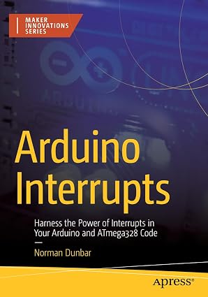
<p><img src="/images/ArduinoInterrupts.cover.jpg" alt="The cover of the Arduino Interrupts book." /></p>

<ul>
  <li><a href="https://link.springer.com/book/10.1007/978-1-4842-9714-8">Get it from Apress</a></li>
  <li><a href="https://www.amazon.co.uk/Arduino-Interrupts-Harness-ATmega328-Innovations/dp/148429713X">Get it from Amazon UK</a></li>
</ul>

<h3 id="from-the-back-cover">From the Back Cover</h3>

<p>Improve your projects by leveraging the power of interrupts. This comprehensive guide makes it easy to understand and use interrupts with the ATmega328P microcontroller found on Arduino boards.</p>

<p>With over 20 interrupts available, this book covers almost all of them and provides background information on how they work. You’ll work through the steps and code examples required to configure each of the covered interrupts. You’ll also learn how to use them with Arduino, AVR C++ and with other development systems, like PlatformIO.</p>

<p>Interrupts can be intimidating, but by the end of this book, you will have the knowledge and skills to take full advantage of them and improve the performance and efficiency of your Arduino projects.</p>

<h3 id="example-sketch">Example Sketch</h3>

<p>The sketch below shows how the ATmega328p’s Watchdog Timer Interrupt can be configured to trigger every second. The interrupt handler will be used to toggle the obligatory LED every time the interrupt is triggered.</p>

<h4 id="configuring-the-watchdog">Configuring the Watchdog</h4>

<pre><code class="language-C">#include "avr/wdt.h"

void WDT_Interrupt(uint8_t timeout) {
    // Save global interrupt flag as we need to restore it to
    // how it was before we turned interrupts off.
    uint8_t oldSREG = SREG;

    // Set the prescaler bits. Get the validated timeout into
    // the correct bits of the wdt_setting variable.
    uint8_t wdt_setting;
    timeout = (timeout &gt; 9) ? 9 : timeout;
    wdt_setting = (timeout &gt; 7) ? (1 &lt;&lt; WDP3) : 0;
    wdt_setting |= (timeout &amp; 7);

    // Disable Interrupts. We don;t want to be interrupted as
    // we are configuring the interrupt itself!
    cli();

    // Reset WDT. In case it is running and ready to reset 
    // the board.
    wdt_reset();

    // Clear RESET by WDT flag. Because we *must* do this.
    MCUSR &amp;= ~(1 &lt;&lt; WDRF);

    // Do the timed sequence. We have 4 clocks to complete
    // the configuration.
    WDTCSR |= ((1 &lt;&lt; WDCE) | (1 &lt;&lt; WDE));

    // Enable interrupts but do not allow the WDT to reset
    // the board, just trigger an interrupt.
    WDTCSR = (wdt_setting) | (1 &lt;&lt; WDIE);

    // REstore global interrupt flag as it was before we 
    // disabled interrupts.
    SREG = oldSREG;
}
</code></pre>

<h4 id="the-setup-function">The <code class="language-plaintext highlighter-rouge">setup()</code> Function</h4>
<pre><code class="language-C">void setup() {
    // The builtin LED on D13 is an OUTPUT.
    pinMode(LED_BUILTIN, OUTPUT);
    
    // Configure the Watchdog Timer &amp; its interrupt.
    WDT_Interrupt(WDTO_1S);
}
</code></pre>

<h4 id="the-loop-function">The <code class="language-plaintext highlighter-rouge">loop()</code> Function</h4>

<pre><code class="language-C">void loop() {
    // Do nothing at all here. The interrupt handler does all
    // the hard work of toggling the builtin LED.
}
</code></pre>

<h4 id="the-watchdog-timer-interrupt-handler">The Watchdog Timer Interrupt Handler</h4>

<div class="language-plaintext highlighter-rouge"><div class="highlight"><pre class="highlight"><code>ISR(WDT_vect) {
    // The Watchdog Timer Interrupt handler. It *must* have
    // the name given here WDT_vect, in exactly that letter
    // case. If not, nothing will blink!
    //
    // All we do here is toggle the builtin LED.
    digitalWrite(13, !digitalRead(13));
}
</code></pre></div></div>

<p>Enjoy.</p>]]></content><author><name></name></author><summary type="html"><![CDATA[My latest book, Arduino Interrupts is now available to read as a paper copy, or as a Kindle or eBook variant.]]></summary></entry><entry><title type="html">Debugging AVR Code with Simulavr</title><link href="https://normandunbar.github.io//2023/10/23/debugging-avr-code-with-simulavr.html" rel="alternate" type="text/html" title="Debugging AVR Code with Simulavr" /><published>2023-10-23T15:02:07+00:00</published><updated>2023-10-23T15:02:07+00:00</updated><id>https://normandunbar.github.io//2023/10/23/debugging-avr-code-with-simulavr</id><content type="html" xml:base="https://normandunbar.github.io//2023/10/23/debugging-avr-code-with-simulavr.html"><![CDATA[<p>When writing AVR code, it can be difficult to debug problems, especially when adding <code class="language-plaintext highlighter-rouge">Serial.printf()</code> calls means that the bug vanishes! Actually, only <code class="language-plaintext highlighter-rouge">Serial.begin()</code> is required to make the bugs vanish.</p>

<p><strong>WARNING</strong>: The simulator hangs if you let the code run and there’s a <code class="language-plaintext highlighter-rouge">delay()</code> call in the code. This <em>may</em> be an artefact of running under gdb – I have yet to test what happens if I just run the code. Might be worth bearing this in mind.</p>

<h3 id="gdb-tutorial">GDB Tutorial</h3>

<p>See <a href="https://www.gdbtutorial.com/gdb_commands" title="https://www.gdbtutorial.com/gdb_commands">https://www.gdbtutorial.com/gdb_commands</a> for a useful gdb tutorial</p>

<h3 id="configuration-and-execution">Configuration and Execution</h3>

<p>In order to use the option Sketch-&gt;Optimize for Debugging in the Arduino IDE, you need to do a little configuration of the IDE to allow that option to have <em>any</em> effect on Arduino boards using the ATmega328P microcontroller. See <a href="/2024/04/03/configure-arduino-ide-for-debugging">this post from the future</a> for details. Once the IDE is correctly configured, you may proceed.</p>

<ol>
  <li>In the Arduino IDE, Sketch-&gt;Optimize for Debugging. Then rebuild the sketch with verbose compilation enabled in preferences.</li>
  <li>In a bash session <code class="language-plaintext highlighter-rouge">cd /tmp/arduino/sketches/LONG_HEX_NUMBER</code> (IDE 1.x.x only) or <code class="language-plaintext highlighter-rouge">~/.cache/arduino/sketches/LONG_HEX_NUMBER</code> (IDE 2.x.x only) which you can see in the compilation output from the previous step.</li>
  <li><code class="language-plaintext highlighter-rouge">simulavr -g -d atmega328 -f SKETCH.ino.elf</code> to start the simulator. You do not need the Arduino board to be running, we are simulating it.</li>
  <li>Your terminal will hang, so open another tab and run:
    <div class="language-bash highlighter-rouge"><div class="highlight"><pre class="highlight"><code><span class="c">## The next line is for IDE 1.x.x only.</span>
<span class="nb">cd</span> /tmp/arduino/sketches/LONG_HEX_NUMBER
   
<span class="c">## The next line is for IDE 2.x.x only.</span>
<span class="nb">cd</span> ~/.cache/arduino/sketches/LONG_HEX_NUMBER
   
<span class="c">## Altogether again from here on.</span>
avr-gdb
file SKETCH.ino.elf
target remote localhost:1212
load
</code></pre></div>    </div>
  </li>
</ol>

<p>You are now running the sketch in the simulator, and using gdb to set breakpoints etc in the normal manner.</p>

<h3 id="useful-gdb-commands">Useful gdb commands</h3>

<p>See also <a href="https://www.gdbtutorial.com/gdb_commands" title="https://www.gdbtutorial.com/gdb_commands">https://www.gdbtutorial.com/gdb_commands</a></p>

<ul>
  <li><code class="language-plaintext highlighter-rouge">b location</code> - sets a breakpoint at <code class="language-plaintext highlighter-rouge">location</code>.</li>
  <li><code class="language-plaintext highlighter-rouge">ir</code> - displays all 32 registers.</li>
  <li><code class="language-plaintext highlighter-rouge">ir r18 r25</code> - displays registers <code class="language-plaintext highlighter-rouge">r18</code> and <code class="language-plaintext highlighter-rouge">r25</code> only.</li>
  <li><code class="language-plaintext highlighter-rouge">p variable</code> - displays the value of a variable.</li>
  <li><code class="language-plaintext highlighter-rouge">p (short)variable</code> - displays the value of a variable as a <code class="language-plaintext highlighter-rouge">short</code> data type.</li>
  <li><code class="language-plaintext highlighter-rouge">continue</code>, <code class="language-plaintext highlighter-rouge">cont</code> or <code class="language-plaintext highlighter-rouge">c</code> - resumes execution after a breakpoint stop.</li>
  <li><code class="language-plaintext highlighter-rouge">step</code> - steps into the next executable instruction.</li>
  <li><code class="language-plaintext highlighter-rouge">next</code> - same as <code class="language-plaintext highlighter-rouge">step</code> but will treat a function call as a single instruction and will stop when the function returns, unlike <code class="language-plaintext highlighter-rouge">step</code>.</li>
  <li><code class="language-plaintext highlighter-rouge">x/FMT ADDRESS</code> - displays a memory dump of <code class="language-plaintext highlighter-rouge">ADDRESS</code> in the specified <code class="language-plaintext highlighter-rouge">FMT</code></li>
</ul>

<h4 id="fmt-specifiers">FMT Specifiers</h4>

<p>The <code class="language-plaintext highlighter-rouge">FMT</code> specifier for the <code class="language-plaintext highlighter-rouge">x</code> command is in three parts:</p>

<ol>
  <li>An optional counter to specify how many “data types” will be displayed.</li>
  <li>The format of the output:
    <ul>
      <li><code class="language-plaintext highlighter-rouge">o</code> = octal</li>
      <li><code class="language-plaintext highlighter-rouge">d</code> = decimal</li>
      <li><code class="language-plaintext highlighter-rouge">x</code> = hexadecimal</li>
      <li><code class="language-plaintext highlighter-rouge">u</code> = unsigned int</li>
      <li><code class="language-plaintext highlighter-rouge">s</code> = string</li>
      <li><code class="language-plaintext highlighter-rouge">t</code> = binary</li>
    </ul>
  </li>
  <li>The data type:
    <ul>
      <li><code class="language-plaintext highlighter-rouge">b</code> = bytes</li>
      <li><code class="language-plaintext highlighter-rouge">h</code> = half words (16 bit)</li>
      <li><code class="language-plaintext highlighter-rouge">w</code> = words (32 bit)</li>
      <li><code class="language-plaintext highlighter-rouge">g</code> = double word (64 bits).</li>
    </ul>
  </li>
</ol>]]></content><author><name></name></author><summary type="html"><![CDATA[When writing AVR code, it can be difficult to debug problems, especially when adding Serial.printf() calls means that the bug vanishes! Actually, only Serial.begin() is required to make the bugs vanish.]]></summary></entry><entry><title type="html">AVR-GCC Register Usage</title><link href="https://normandunbar.github.io//2023/10/23/avr-gcc-register-usage.html" rel="alternate" type="text/html" title="AVR-GCC Register Usage" /><published>2023-10-23T14:39:07+00:00</published><updated>2023-10-23T14:39:07+00:00</updated><id>https://normandunbar.github.io//2023/10/23/avr-gcc-register-usage</id><content type="html" xml:base="https://normandunbar.github.io//2023/10/23/avr-gcc-register-usage.html"><![CDATA[<p>When writing AVR assembly code, there are protocols that must be followed when using and abusing the various registers available in the ATmega328P device, which is what I’m using, built in to many Arduino boards.</p>

<p>The assembly language written can be compiled in the Arduino IDE using the GCC/G++ compiler controller and this, in turn, will call the avr-as assembler to do the actual work. All you need to do is add a new file to your Arduino sketch, and name it <code class="language-plaintext highlighter-rouge">*.S</code> where the name can be anything, but the extension <em>must</em> be an upper case ‘S’.</p>

<h3 id="special-registers">Special Registers</h3>

<p>The compiler makes use of registers as described in the following sections.</p>

<h4 id="r0-temporary-register">R0: Temporary Register</h4>

<p><code class="language-plaintext highlighter-rouge">R0</code> is the temporary register used by the C++ compiler generated code. To this end, it <em>must</em> be preserved by the assembly code if it is used there. Obviously, it should also be restored before calling or returning to C++.</p>

<h4 id="r1-zero-register">R1: Zero Register</h4>

<p><code class="language-plaintext highlighter-rouge">R1</code> is the zero register. The code generated by the C++ compiler expects the register toalways hold the value zero. If your assembly code uses this register for any reason, it <em>must</em> be cleared back to zero before calling or returning to C++.</p>

<h3 id="call-saved-registers">Call Saved Registers</h3>

<p><code class="language-plaintext highlighter-rouge">R2</code>-<code class="language-plaintext highlighter-rouge">R17</code> plus <code class="language-plaintext highlighter-rouge">R28</code> and <code class="language-plaintext highlighter-rouge">R29</code> are the <em>Call Saved Registers</em>. What this means is that these <em>must</em> be saved if they are used in your assembly code, and restored before calling or returning to C++.</p>

<h3 id="call-clobbered-registers">Call Clobbered Registers</h3>

<p><code class="language-plaintext highlighter-rouge">R18</code>-<code class="language-plaintext highlighter-rouge">R27</code> plus <code class="language-plaintext highlighter-rouge">R30</code> and <code class="language-plaintext highlighter-rouge">R31</code> are the <em>Call Used/Clobbered Registers</em>. What this means is that these can be used freely in your assembly code, however, they are clobbered by the C++ compiler’s generated code, so if you call a C++ function, you <em>must</em> preserve them if you have values in them which you will use on return from the C++ call.</p>

<h3 id="summary">Summary</h3>

<table>
  <thead>
    <tr>
      <th style="text-align: left">Register</th>
      <th style="text-align: left">Category</th>
      <th style="text-align: left">Special Considerations</th>
    </tr>
  </thead>
  <tbody>
    <tr>
      <td style="text-align: left">R0</td>
      <td style="text-align: left">Temporary</td>
      <td style="text-align: left">Must be preserved if used by assembly code, and restored before calling or returning to C++ code.</td>
    </tr>
    <tr>
      <td style="text-align: left">R1</td>
      <td style="text-align: left">Zero Register</td>
      <td style="text-align: left">Must be cleared to zero before calling or returning to C++.</td>
    </tr>
    <tr>
      <td style="text-align: left">R2 to R17</td>
      <td style="text-align: left">Call Saved</td>
      <td style="text-align: left">If used in assembly code, must have their values preserved before use, and restored before calling or returning to C++.</td>
    </tr>
    <tr>
      <td style="text-align: left">R18 to R27</td>
      <td style="text-align: left">Call Clobbered</td>
      <td style="text-align: left">If used in assembly code, must have their values preserved before calling C++ functions, and restored on return.</td>
    </tr>
    <tr>
      <td style="text-align: left">R28 and R29</td>
      <td style="text-align: left">Call Saved</td>
      <td style="text-align: left">If used in assembly code, must have their values preserved before use, and restored before calling or returning to C++.</td>
    </tr>
    <tr>
      <td style="text-align: left">R30 and R31</td>
      <td style="text-align: left">Call Clobbered</td>
      <td style="text-align: left">If used in assembly code, must have their values preserved before calling C++ functions, and restored on return.</td>
    </tr>
  </tbody>
</table>]]></content><author><name></name></author><summary type="html"><![CDATA[When writing AVR assembly code, there are protocols that must be followed when using and abusing the various registers available in the ATmega328P device, which is what I’m using, built in to many Arduino boards.]]></summary></entry><entry><title type="html">Configuring Linux Mint to use my UHD Laptop Display</title><link href="https://normandunbar.github.io//2023/10/21/configure-linux-mint-laptop.html" rel="alternate" type="text/html" title="Configuring Linux Mint to use my UHD Laptop Display" /><published>2023-10-21T14:30:07+00:00</published><updated>2023-10-21T14:30:07+00:00</updated><id>https://normandunbar.github.io//2023/10/21/configure-linux-mint-laptop</id><content type="html" xml:base="https://normandunbar.github.io//2023/10/21/configure-linux-mint-laptop.html"><![CDATA[<p>My Linux Mint installation on my laptop has a wee problem with the extreme resolution of the laptop display. This is 3072 by 1920 (16:10) and when an application is opened on the laptop screen, it is tiny. I need to fix it, so this is what I do when I install a new release.</p>

<h3 id="display-properties">Display Properties</h3>

<ul>
  <li>LM -&gt; Preferences -&gt; Display.</li>
  <li>Settings tab:
    <ul>
      <li>Make sure “Enable fractional scaling controls” is on.</li>
      <li>Set “Scale content up” for “Fractional scaling mode”.</li>
    </ul>
  </li>
  <li>Layout Tab:
    <ul>
      <li>Make sure “Monitor Scale” is 100% for the laptop screen. I use 75% for the second screen.</li>
    </ul>
  </li>
</ul>

<p>Repeat for all monitors. I have two.</p>

<h3 id="fonts">Fonts</h3>

<ul>
  <li>LM -&gt; Preferences -&gt; System Settings</li>
  <li>Font Selection:
    <ul>
      <li>Choose your preferred font and sizes. Mine are the default, “Ubuntu Regular 10” for most of the options; Monospace is “DejaVu Sans Mono Book”; and Window title is “Ubuntu Medium 10”.</li>
    </ul>
  </li>
  <li>Font Settings:
    <ul>
      <li>Set “Text scaling factor” to 1.3, 1.4 or 1.5 as you prefer. Mine is 1.4.</li>
    </ul>
  </li>
</ul>

<h3 id="desktop-panel">Desktop Panel</h3>

<p>Next, the desktop panel (the task bar if you want the Windows terminology!) might need adjusting. My primary monitor is the UHD laptop, so the panel is a wee bit thin for my eyes these days!</p>

<ul>
  <li>Right-click the panel.</li>
  <li>Choose “Panel Settings”</li>
  <li>Click “Left Zone”
    <ul>
      <li>Adjust the panel height, mine is 44 pixies tall. (Affects all zones)</li>
      <li>Set the “Font size” to “Allow theme to determine font size”.</li>
      <li>Set “Coloured icon size” to “Scale to panel size optimally”, or, “Scale to panel size exactly” if you prefer.</li>
    </ul>
  </li>
  <li>Click “Right Zone”
    <ul>
      <li>Set the “Font size” to “Allow theme to determine font size”.</li>
      <li>Set “Coloured icon -&gt; Preferences -&gt; System Settings size” to <strong>Scale to panel size optimally</strong>, or, <strong>Scale to panel size exactly</strong> if you prefer.</li>
      <li>Adjust “Symbolic icon size” to 32 pixies or to match any coloured icons you have on the right side. I have HPLIP over on the right so that sizes automagically, but the symbolic icons (monocolour) look tiny next to it.</li>
    </ul>
  </li>
</ul>

<p>I don’t have anything to worry about in the “Centre Zone” but if I ever do, I can adjust accordingly.</p>

<h3 id="mouse">Mouse</h3>

<p>The mouse pointer looks ridiculously tiny on the UHD monitor, so:</p>

<ul>
  <li>LM -&gt; Preferences -&gt; Mouse and Touchpad
    <ul>
      <li>Adjust the pointer size on the UHD monitor until it looks a bit more visible. I ended up at a position 65% of the way along the slider.</li>
    </ul>
  </li>
</ul>

<h3 id="reboot-now">Reboot, Now!</h3>

<p>Reboot the laptop even though it <em>appears</em> to have all been changed correctly, you get “funnies” if you don’t do a reboot.</p>

<h3 id="second-monitor">Second Monitor</h3>

<p>As my second monitor is only a 1920 by 1080 (16:9 HD) one, the fonts appear to be quite large when an application is moved onto that monitor. Nothing too onerous, but if the standard settings don’t look right, we need to go back to scaling.</p>

<p>This saves mucking about with the scaling, however, if the two monitors were too far apart in terms of size, it might be a better plan to:</p>

<ul>
  <li>Set the font scaling back to 1.0.</li>
  <li>Turn on fractional scaling again and set it to 75%</li>
  <li>Set each monitor’s scaling individually.</li>
</ul>

<p>I did try this, but wasn’t too happy with 125% for the laptop and 100% for the HD monitor. Your mileage, as they say. may vary.</p>]]></content><author><name></name></author><summary type="html"><![CDATA[My Linux Mint installation on my laptop has a wee problem with the extreme resolution of the laptop display. This is 3072 by 1920 (16:10) and when an application is opened on the laptop screen, it is tiny. I need to fix it, so this is what I do when I install a new release.]]></summary></entry><entry><title type="html">Messing About with Samba Shares on my Volumio Server</title><link href="https://normandunbar.github.io//2023/04/15/messing-with-samba-shares-for-volumio.html" rel="alternate" type="text/html" title="Messing About with Samba Shares on my Volumio Server" /><published>2023-04-15T13:47:02+00:00</published><updated>2023-04-15T13:47:02+00:00</updated><id>https://normandunbar.github.io//2023/04/15/messing-with-samba-shares-for-volumio</id><content type="html" xml:base="https://normandunbar.github.io//2023/04/15/messing-with-samba-shares-for-volumio.html"><![CDATA[<p>As you might know, if you have read my two previous posts, I have a <a href="https://www.raspberrypi.com/" title="https://www.raspberrypi.com/">Raspberry Pi 3</a> set up as a Music <em>player</em> using <a href="https://volumio.com" title="https://volumio.com">Volumio</a> and while this is excellent when I’m sat at my laptop – probably writing another Arduino book! – I can’t play my music from my tablet or phone while elsewhere in the house. I still want to install <a href="https://mstream.io" title="https://mstream.io">MStream</a> so I’m no setting up a second Raspberry Pi to install MStream on, ad hopefully, get it to read all the music from the Volumio server.</p>

<p>I have already installed <a href="https://bubbleupnp.en.uptodown.com/android" title="https://bubbleupnp.en.uptodown.com/android">Bubble UPNP</a>, from the Google Play Store, onto my phone and tablet. This app comes highly recommended. Unfortunately, in the free version, playlists are limited to 16 tracks only, and many of my albums have more tracks that this. So, unless I upgrade and pay (!) or mess around with playlists consisting of the first 16 tracks then the remainder, I’m not sure this is the best option for me, especially when the MStream Android app is so good – I’ve been running it connected to their own demo server, and it’s brilliant!</p>

<h2 id="useful-samba-links">Useful SAMBA Links</h2>

<p>I found the information on the following links to be extremely helpful in setting up my SAMBA shares.</p>

<ul>
  <li><a href="https://linuxconfig.org/how-to-configure-samba-server-share-on-ubuntu-20-04-focal-fossa-linux" title="https://linuxconfig.org/how-to-configure-samba-server-share-on-ubuntu-20-04-focal-fossa-linux">Configuring Samba</a></li>
  <li><a href="https://linuxconfig.org/how-to-mount-a-samba-shared-directory-at-boot" title="https://linuxconfig.org/how-to-mount-a-samba-shared-directory-at-boot">Mounting SAMBA shares at boot time</a></li>
</ul>

<h2 id="configuring-the-volumio-server">Configuring the Volumio Server</h2>

<p>The first task is to get onto the Volumio server to set up a new, read only, share that other devices can mount and see all the USB attached thumb drives I store my music on. In theory, this should also allow them to see any new drives that I add.</p>

<p>To configure SAMBA, I need to be root, but I’m logged in as volumio, no worries:</p>

<div class="language-bash highlighter-rouge"><div class="highlight"><pre class="highlight"><code><span class="nb">sudo</span> <span class="nt">-i</span>
cs /etc/samba
</code></pre></div></div>

<p>Now, create a backup before editing the configuration file, <code class="language-plaintext highlighter-rouge">smb.conf</code>:</p>

<div class="language-bash highlighter-rouge"><div class="highlight"><pre class="highlight"><code><span class="nb">cp </span>smb.conf smb.conf.backup.ND
nano smb.conf
</code></pre></div></div>

<p>In the editor, we can see that there are three SAMBA mounts defined:</p>

<ul>
  <li>Internal Storage on <code class="language-plaintext highlighter-rouge">/data/internal</code>, we are not interested in this one.</li>
  <li>NAS on <code class="language-plaintext highlighter-rouge">/mnt/NAS</code>, again, we are not interested.</li>
  <li>USB on <code class="language-plaintext highlighter-rouge">/mnt/USB</code>, and this one, we are most definitely interested in!</li>
</ul>

<p>These are configured as read-write, but I don’t want to allow everyone and their dog to write all over my music collection, so I’ll be setting up a new share which will be read only. At the bottom of the file, add the following text:</p>

<div class="language-text highlighter-rouge"><div class="highlight"><pre class="highlight"><code>[MSTREAM]
        # This allows anonymous (guest) access
        # without authentication. 
        # Only USB mounts are accessible, read only access.
        path = /mnt/USB
        read only = yes
        guest ok = yes
        guest only = yes
</code></pre></div></div>

<p>After saving the file with <code class="language-plaintext highlighter-rouge">CTRL-X, Y, ENTER</code> we need to restart the SAMBA daemon, <code class="language-plaintext highlighter-rouge">smbd</code>:</p>

<div class="language-bash highlighter-rouge"><div class="highlight"><pre class="highlight"><code>systemctl restart smbd
</code></pre></div></div>

<h2 id="testing-the-new-samba-share">Testing the New SAMBA Share</h2>

<p>On a different device – laptop or Raspberry Pi – I can test if the new share is available as follows.</p>

<p>First, we need our own user’s user and group ids:</p>

<div class="language-bash highlighter-rouge"><div class="highlight"><pre class="highlight"><code><span class="nb">id

</span><span class="nv">uid</span><span class="o">=</span>1000<span class="o">(</span>norman<span class="o">)</span> <span class="nv">gid</span><span class="o">=</span>1000<span class="o">(</span>norman<span class="o">)</span> <span class="nb">groups</span><span class="o">=</span>.....
</code></pre></div></div>

<p>You will need to substitute your own user and group ids as necessary. Now we can run the test:</p>

<div class="language-bash highlighter-rouge"><div class="highlight"><pre class="highlight"><code><span class="nb">sudo</span> <span class="nt">-i</span>    <span class="c">## If necessary, we need to be root.</span>
<span class="nb">mkdir</span> <span class="nt">-p</span> /mnt/mstream
mount <span class="nt">-t</span> cifs  <span class="nt">-o</span> guest <span class="nt">-o</span> <span class="nv">uid</span><span class="o">=</span>1000 <span class="nt">-o</span> <span class="nv">gid</span><span class="o">=</span>1000 //192.168.1.41/MSTREAM /mnt/mstream
</code></pre></div></div>

<p>Assuming that the <code class="language-plaintext highlighter-rouge">mount</code> command, above, comes back with no errors, then we should be able to see my mounted USB devices on the remote Volumio server:</p>

<div class="language-bash highlighter-rouge"><div class="highlight"><pre class="highlight"><code><span class="nb">ls </span>mnt/mstream

0959-0DF7  30E5-1614
</code></pre></div></div>

<p>And, check within one of them:</p>

<div class="language-bash highlighter-rouge"><div class="highlight"><pre class="highlight"><code><span class="nb">ls </span>mnt/mstream/0959-0DF7

<span class="s1">'Alice Cooper'</span>                   <span class="s1">'Journey'</span>
<span class="s1">'Amy MacDonald'</span>                  <span class="s1">'Kate Bush'</span>
<span class="s1">'Anderson Bruford Wakeman Howe'</span>  <span class="s1">'Katie Melua'</span>
<span class="s1">'Andrea Bocelli'</span>                 <span class="s1">'Marillion'</span>
...                              ...
</code></pre></div></div>

<p>So, it all seems to be working. Unmount the test and, if necessary, remove the mount point if it is no longer needed. In my case, it will hopefully be used when I install MStream, so I’m leaving it, for now at least. We should still be logged into root through the <code class="language-plaintext highlighter-rouge">sudo -i</code> command earlier.</p>

<div class="language-bash highlighter-rouge"><div class="highlight"><pre class="highlight"><code><span class="nb">sudo </span>umount /mnt/mstream
<span class="nb">sudo rmdir</span> /mnt/mstream    <span class="c">## If mount is test only and no longer required.</span>
</code></pre></div></div>

<h2 id="configure-the-client-device">Configure the Client Device</h2>

<p>We would like the client device, where MStream is to be installed, to mount the SAMBA share at boot time. To do this we need to edit <code class="language-plaintext highlighter-rouge">/etc/fstab</code> on the client machine:</p>

<div class="language-bash highlighter-rouge"><div class="highlight"><pre class="highlight"><code><span class="nb">sudo </span>vi /etc/fstab
</code></pre></div></div>

<p>Add a single line of text to the file, at the end is probably best:</p>

<div class="language-text highlighter-rouge"><div class="highlight"><pre class="highlight"><code>//192.168.1.41/MSTREAM /mnt/mstream cifs uid=1000,gid=1000,guest 0 0
</code></pre></div></div>

<p>We can test this with:</p>

<div class="language-bash highlighter-rouge"><div class="highlight"><pre class="highlight"><code><span class="nb">sudo </span>mount <span class="nt">-a</span>
<span class="nb">ls </span>mnt/mstream

0959-0DF7  30E5-1614
</code></pre></div></div>]]></content><author><name></name></author><summary type="html"><![CDATA[As you might know, if you have read my two previous posts, I have a Raspberry Pi 3 set up as a Music player using Volumio and while this is excellent when I’m sat at my laptop – probably writing another Arduino book! – I can’t play my music from my tablet or phone while elsewhere in the house. I still want to install MStream so I’m no setting up a second Raspberry Pi to install MStream on, ad hopefully, get it to read all the music from the Volumio server.]]></summary></entry><entry><title type="html">Streaming Music from my Volumio Server</title><link href="https://normandunbar.github.io//2023/04/14/streaming-music-from-volumio.html" rel="alternate" type="text/html" title="Streaming Music from my Volumio Server" /><published>2023-04-14T14:17:02+00:00</published><updated>2023-04-14T14:17:02+00:00</updated><id>https://normandunbar.github.io//2023/04/14/streaming-music-from-volumio</id><content type="html" xml:base="https://normandunbar.github.io//2023/04/14/streaming-music-from-volumio.html"><![CDATA[<p>I have a <a href="https://www.raspberrypi.com/" title="https://www.raspberrypi.com/">Raspberry Pi</a> set up as a Music <em>player</em> using <a href="https://volumio.com" title="https://volumio.com">Volumio</a> and while this is excellent when I’m sat at my laptop – probably writing another Arduino book! – I can’t play my music from my tablet ot phone while elsewhere in the house. My original plan was to install <a href="https://mstream.io" title="https://mstream.io">MStream</a> but thanks to the way that Volumio takes over the Pi, I was unable to install the MStream dependencies, <em>nodejs</em> and <em>npm</em> to that was a bummer straight away. However, this turned out to be quite simple to fix, although I had to kisss MStream goodbye at this point.</p>

<p>I first installed <a href="https://bubbleupnp.en.uptodown.com/android" title="https://bubbleupnp.en.uptodown.com/android">Bubble UPNP</a>, from the Google Play Store, onto my phone and tablet. This app comes highly recommended. There is a free – with ads – version and a £3.99 pay for version. Being Scottish and living in Yorkshire, I have two reputations for meanness to live down to, so I went for the free version. This is especially handy as I’m using <a href="https://pi-hole.net" title="https://pi-hole.net">Pi Hole</a> to block ads anyway.</p>

<p>After installing BubBle UPNP, I opened it, and opened the <em>Local and Cloud</em> option and set up a pair of servers, <em>Volumio One</em> and <em>Volumio Two</em> – meaningful names eh? These were configured as <em>SMB</em> (Samba) server types and mapped to the two large USB thumb drives I’m using on the Raspberry Pi to hold my music.</p>

<p>Now I can stream music from my Volumio server to my devices. Easy!</p>

<p>I could have just set up a single Volumio server and left the optional folder blank, but then I’d have had to navigate to USB then to one or other of the devices – and they have very unmeaningful names – so I preferred to do it as described above. I simply open one or other server and pick a folder to play. Job done.</p>]]></content><author><name></name></author><summary type="html"><![CDATA[I have a Raspberry Pi set up as a Music player using Volumio and while this is excellent when I’m sat at my laptop – probably writing another Arduino book! – I can’t play my music from my tablet ot phone while elsewhere in the house. My original plan was to install MStream but thanks to the way that Volumio takes over the Pi, I was unable to install the MStream dependencies, nodejs and npm to that was a bummer straight away. However, this turned out to be quite simple to fix, although I had to kisss MStream goodbye at this point.]]></summary></entry></feed>